SHIDAH
by
HILARY MEDIA
on
07:47
 er
er

1.  Processor socket
2.  Chipset
3.  RAM slots
4.  AGP graphic card slot
5.  PCI slots
6.  CNR modem slot
7.  Audio chip
8.  I/O chip
9.  BIOS
10. ATX power connector
11. Floppy drive connector
12. ATA connectors
13. Connectors for buttons,
    indicator lights etc.
The external ports (connections) are along the top edge (right hand side). A face-on view is shown below.
|

The important constituent components of an ATX Motherboard are given below:
|


Memory modules are printed circuit cards made up of memory chips, and a few
other passive components. Normally, memory modules are the those that get
installed on the motherboard's memory slots, and you don't handle individual
memory chips. The following are the prominently used memory modules (also called
memory cards):
|
 |
Typical DIMM package (using DDRAM):
Memory size: 256MB
Pins:168 pin
|
 |
A RIMM package using RDRAM |
 |
|
| Socket type: Socket 478 (mPGA478B) |
 |
 |
 |
| Socket A | Processor for Socket A |
 |
 |
| BIOS chip | BIOS chip after insertion into a socket. |


 | ||||
| TIMU YA SEMESTER ONE |
 | ||||||
| kipa wa semester one akishagilia ushindi |


|
1. Back Panel Connectors &
Ports
|
Connectors and ports for
connecting the computer to external devices such as display ports, audio
ports, USB ports, Ethernet ports, PS/2 ports etc. See image below for a
close-up view.
For details on the individual back panel ports, |
|
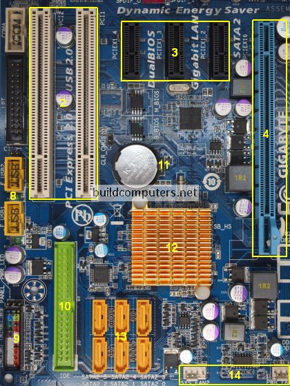
2. PCI Slots
3. PCI Express x1 Slots 4. PCI Express x16 Slot 5. Northbridge 6. CPU Socket 7. ATX 12V Power Connector |
PCI: Peripheral Component
Interconnect
Slot for older expansion cards such as sound cards, network cards, connector cards. See image below for a close-up view. Have been largely replaced by PCI-Express x1 slots (see motherboard parts #3 below). Slot for modern expansion cards such as sound cards, network cards (Wi-Fi, Ethernet, Bluetooth), connector cards (USB, FireWire, eSATA) and certain low-end graphics cards. See image below for a close-up view. Slot for discrete graphic cards and high bandwidth devices such as top-end solid state drives. See image below for a close-up view. Also known as Memory Controller Hub (MCH). Chipset that allows the CPU to communicate with the RAM and graphics card. Beginning from the Sandy Bridge generation of Intel CPUs, motherboards no longer have this component as it has been integrated within the CPU itself. Insert CPU here. To learn how to install a CPU, Connects to the 4-pin power cable of a power supply unit which supplies power to the CPU. |
|
8. Front Panel USB 2.0 Connectors
9. Front Panel Connectors 10. IDE Connector 11. CMOS Battery 12. Southbridge 13. SATA Connectors 14. Fan Headers 15. RAM Slots 16. ATX Power Connector |
Connects to USB 2.0 ports at the
front or top of a computer case. See image above for a close-up view.
Connects to the power switch, reset switch, power LED, hard drive LED and front audio ports of a computer case. See image above for a close-up view. For more details on the individual front panel ports,
Connects to older hard drive disks and optical drives for data transfer. See
image above for a close-up view.
Have been replaced over by SATA connectors (see motherboard components #13 below). Supplies power to store BIOS settings and keep the real-time clock running. See image above for a close-up view. The CMOS battery found on most motherboards is the CR2032 lithium coin cell. Also known as the Input/Output Controller Hub (ICH). Chipset that allows the CPU to communicate with PCI slots, PCI-Express x 1 slots (expansion cards), SATA connectors (hard drives, optical drives), USB ports (USB devices), Ethernet ports and on-board audio. Connects to modern hard disk drives, solid state drives and optical drives for data transfer. See image above for a close-up view.
Supplies power to the CPU heat sink fan and computer case fans. See image
above for a close-up view.
Insert RAM here. To learn how to install RAM
Connects to the 24-pin ATX power cable of a power supply unit which supplies
power to the motherboard.
|
|
17. mSATA Connector
18. Front Panel USB 3.0 Connector 19. Power & Reset Button |
Connects to a mSATA solid state
drive. In most cases, this SSD is used as cache to speed up hard disk drives,
but it's possible to re-purpose it as a regular hard drive.
Connects to USB 3.0 ports at the front or top of the computer case.
Onboard button to turn on, turn off and reboot the computer.
This motherboard component is more common among high end boards. |
| 1. Back Panel Connectors & Ports | Connectors and ports for connecting the computer to external devices such as
display ports, audio ports, USB ports, Ethernet ports, PS/2 ports etc.
See image below for a close-up view. For details on the individual back panel ports, click here for our guide to computer cable connections. |
| 2. PCI Slots 3. PCI Express x1 Slots 4. PCI Express x16 Slot 5. Northbridge 6. CPU Socket 7. ATX 12V Power Connector | PCI: Peripheral Component Interconnect Slot for older expansion cards such as sound cards, network cards, connector cards. See image below for a close-up view. Have been largely replaced by PCI-Express x1 slots (see motherboard parts #3 below). Slot for modern expansion cards such as sound cards, network cards (Wi-Fi, Ethernet, Bluetooth), connector cards (USB, FireWire, eSATA) and certain low-end graphics cards. See image below for a close-up view. Slot for discrete graphic cards and high bandwidth devices such as top-end solid state drives. See image below for a close-up view. Also known as Memory Controller Hub (MCH). Chipset that allows the CPU to communicate with the RAM and graphics card. Beginning from the Sandy Bridge generation of Intel CPUs, motherboards no longer have this component as it has been integrated within the CPU itself. Insert CPU here. To learn how to install a CPU, click here for our guide to installing a CPU. Connects to the 4-pin power cable of a power supply unit which supplies power to the CPU. |
| 8. Front Panel USB 2.0 Connectors 9. Front Panel Connectors 10. IDE Connector 11. CMOS Battery 12. Southbridge 13. SATA Connectors 14. Fan Headers 15. RAM Slots 16. ATX Power Connector | Connects to USB 2.0 ports at the front or top of a computer case. See image above for a close-up view. Connects to the power switch, reset switch, power LED, hard drive LED and front audio ports of a computer case. See image above for a close-up view. For more details on the individual front panel ports, click here for our guide to installing a motherboard. Connects to older hard drive disks and optical drives for data transfer. See image above for a close-up view. Have been replaced over by SATA connectors (see motherboard components #13 below). Supplies power to store BIOS settings and keep the real-time clock running. See image above for a close-up view. The CMOS battery found on most motherboards is the CR2032 lithium coin cell. Also known as the Input/Output Controller Hub (ICH). Chipset that allows the CPU to communicate with PCI slots, PCI-Express x 1 slots (expansion cards), SATA connectors (hard drives, optical drives), USB ports (USB devices), Ethernet ports and on-board audio. Connects to modern hard disk drives, solid state drives and optical drives for data transfer. See image above for a close-up view. Supplies power to the CPU heat sink fan and computer case fans. See image above for a close-up view. Insert RAM here. To learn how to install RAM, click here for our guide to installing RAM. Connects to the 24-pin ATX power cable of a power supply unit which supplies power to the motherboard. |
| 17. mSATA Connector 18. Front Panel USB 3.0 Connector 19. Power & Reset Button | Connects to a mSATA solid state drive. In most cases, this SSD is
used as cache to speed up hard disk drives, but it's possible to
re-purpose it as a regular hard drive. Connects to USB 3.0 ports at the front or top of the computer case. Onboard button to turn on, turn off and reboot the computer. This motherboard component is more common among high end boards. |


 N
N


